
1. Introduction
In a complete wire drawing production line, the drawing machine is the core equipment responsible for reducing wire diameter and improving surface quality. However, the continuous and stable operation of the drawing process cannot rely on the drawing machine alone. Various auxiliary equipment is required to ensure smooth wire feeding, reliable connection between wire coils, and efficient production.
Among all wire drawing auxiliary equipment, the Wire Pointing Machine and Wire Welding Machine are two of the most important devices. The Wire Pointing Machine is mainly used for reducing the diameter of rod materials before threading through the drawing dies, while the welding machine is used to connect wire ends during continuous drawing production. These machines greatly improve production efficiency, reduce manual operation, and ensure stable operation of the entire wire drawing process.
2. Wire Pointing Machine for Wire Drawing
2.1 Function of Wire Pointing Machine
2.1.1 Wire Pointing Machine is an important auxiliary device used before wire drawing.
2.1.2 Its main function is to reduce the diameter of copper rods, aluminum rods, or other metal rods by rolling, creating a smaller pointed section that can easily pass through the drawing die.
2.1.3 During the wire drawing process, the original rod diameter is usually much larger than the opening of the first drawing die.
2.1.4 Therefore, the wire end must be reduced and shaped before entering the die.
2.1.5 The Wire Pointing Machine performs this preparation process, allowing the operator to easily insert the wire into the drawing die and start production.
2.1.6 In practical applications, Wire Pointing Machines are mainly equipped in coarse drawing lines and medium drawing lines, while Fine Wire Drawing Machines usually do not require this equipment because the incoming wire diameter is already relatively small.
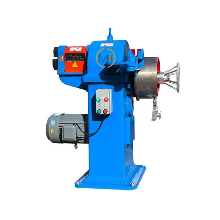
2.2 Main Structure of Wire Pointing Machine
2.2.1 Worm gear reducer motor: The motor provides the driving force, while the worm gear reducer controls the rotating speed and increases the output torque.
2.2.2 Gear box: The gear transmission system transfers power to the rolling components and ensures synchronized operation of the rollers.
2.2.3 Pointing drum: The drum cooperates with the friction wheel to feed the wire into the drawing die.
2.2.4 Rolling rollers: The rollers contain specially designed holes with different diameters. They gradually reduce the wire cross-section through repeated rolling.
2.2.5 Wire pointing device: It forms the reduced wire end, making it suitable for die threading.
2.2.6 Cutting pliers: Used for cutting the wire end after pointing or removing unnecessary material.
2.3 Working Principle of Wire Pointing Machine
2.3.1 The Wire Pointing Machine works through a pair of upper and lower rolling rollers.
2.3.2 These rollers rotate periodically in opposite directions with a rotation angle of approximately 180°.
2.3.3 The hole shape inside the rollers follows a cycle: Large diameter → Small diameter → Large diameter.
2.3.4 When the roller opening reaches the largest position, the wire material enters smoothly.
2.3.5 As the rollers continue rotating, the opening gradually becomes smaller, applying pressure to the wire and reducing its cross-sectional area evenly.
2.3.6 Through repeated rolling cycles, the rod gradually becomes thinner and forms a pointed section suitable for threading into the drawing die.
2.3.7 The pointing drum works together with the friction wheel: When rotating clockwise, the drum drives the wire forward into the die. When rotating counterclockwise, the drum rotates freely without feeding the wire.
2.3.8 This design ensures stable wire feeding while avoiding unnecessary resistance.
2.4 Operation Process and Important Details
2.4.1 Periodic Rolling Process
(1) During operation, the shaped rollers continuously perform a periodic rolling movement.
(2) When the roller hole is large, the wire is positioned and pushed forward.
(3) As the hole size decreases, the metal material is compressed evenly from all directions, reducing the diameter gradually.
(4) This process avoids sudden deformation and prevents cracks caused by excessive reduction.
2.4.2 Preventing Edge Flash Formation
(1) During rolling, excessive material extrusion may occur at the wire edge, creating unwanted metal flashes.
(2) These flashes may affect the threading process and cause difficulty when passing through the drawing die.
(3) To prevent this problem, the wire should be rotated approximately 90°after each rolling operation.
(4) The rotation allows the deformation force to act evenly around the wire surface, resulting in a more uniform pointed shape and better threading performance.
3. Wire Welding Machine for Wire Drawing
3.1 Hot Welding Machine
3.1.1 Working Principle
(1) Resistance welding uses electrical resistance heat generated when a large current passes through the contact area between two metal wire ends.
(2) When current flows through the contact point, the electrical resistance converts electrical energy into heat energy, causing the wire ends to become red-hot or reach a plastic state.
(3) At the same time, an axial pressure is applied to force the two softened ends together, forming a strong welded joint.
(4) The welding process includes: Clamping the two wire ends. Applying a large welding current. Heating the contact area through resistance. Applying upsetting pressure. Cooling and completing the welded joint.
(5) The upsetting force compresses and enlarges the heated wire ends, making the connection firm and compact.
3.1.2 Main Components of Resistance Welding Machine
(1) Fixed Clamp and Moving Clamp: The clamps hold the wire ends securely and conduct welding current.
(2) Welding Wire: The two wire ends that need to be connected.
(3) Transformer System: The primary and secondary windings form the welding transformer. The transformer converts normal voltage into low voltage and high current suitable for welding.
(4) Upsetting Pressure Device: After heating, the device provides axial compression force to join the two wire ends together.
3.1.3 Advantages of Resistance Welding
(1) Resistance welding has several advantages: High welding efficiency, Low production cost, Suitable for copper, aluminum, and other highly conductive materials, Reliable welded joints, High production speed, Easy automation, Good working environment.
(2) Because of these advantages, resistance welding is widely used in large wire drawing production lines. However, welding parameters must be carefully controlled.
(3) The welding current and heating time must be adjusted properly. Excessive heating may cause: Grain growth, Reduced mechanical strength, Lower elongation
Increased brittleness.
(4) Therefore, some welded joints may require additional electrical annealing treatment before entering high-speed drawing processes.
3.2 Cold Pressure Welding Machine
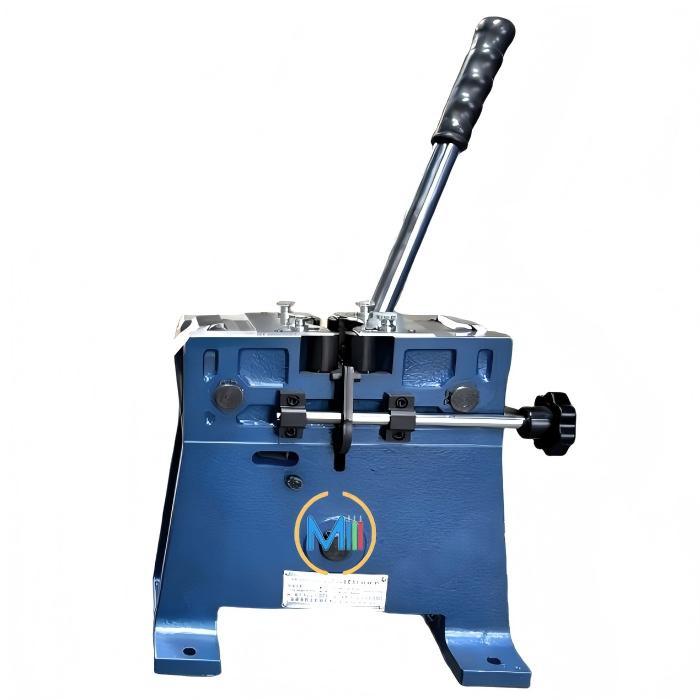
3.2.1 Working Principle
(1) Unlike resistance welding, cold pressure welding does not use external heat energy.
(2) Instead, it relies completely on extremely high mechanical pressure to create a solid-state connection.
(3) During the welding process: The wire ends are placed inside a special welding die.
Strong pressure is applied. The metal undergoes severe plastic deformation. Surface oxide layers and impurities are broken and squeezed out. Clean metal surfaces come into direct contact. Atomic bonding occurs between the two metal surfaces.
(4) As a result, the two wire ends become permanently connected without melting.
3.2.2 Advantages of Cold Pressure Welding Machine
(1) No Heat-Affected Zone: Since no external heating is applied, the welded area does not experience thermal damage. The original mechanical properties and electrical conductivity of the wire are maintained.
(2) Excellent Joint Quality: The welded joint has high tensile strength, good elongation, stable electrical conductivity, smooth surface quality. The joint can directly enter subsequent high-speed drawing processes.
(3) Easy Removal of Welding Flash: The small amount of extruded material is thin and brittle, making it easy to remove manually.
3.2.3 Disadvantages of Cold Pressure Welding Machine
(1) High Requirements for Welding Dies: The welding die must have high machining accuracy, high hardness, excellent wear resistance, poor-quality dies may cause unstable welding results.
(2) Limited Die Compatibility: Different wire diameters usually require different welding dies. Therefore, the flexibility of cold welding equipment is lower compared with hot welding.
(3) Higher Equipment Cost: Cold welding machines usually have more precise mechanical structures and higher manufacturing costs. Regular maintenance is also required to prevent die damage, metal chips accumulation, incorrect positioning.
4. Comparison Between Hot Welding and Cold Pressure Welding
| Comparison | Hot Welding | Cold Pressure Welding |
| Energy Source | Heat energy generated by electrical resistance plus pressure | Mechanical pressure only |
| Welding Mechanism | Metal is heated, softened, and combined under pressure | Metal surfaces are plastically deformed and bonded at atomic level |
| Heat Effect | Produces heat-affected zone (HAZ) | No heat-affected zone |
| Mechanical Performance | May reduce strength and elongation due to heating | Maintains original wire properties |
| Electrical Performance | Possible slight increase in resistance | Almost unchanged conductivity |
| Surface Quality | Larger welding flash requiring grinding | Small flash easily removed |
| Suitable Materials | Copper, aluminum, large diameter wires, special materials | Copper, aluminum, brass, aluminum alloy |
| Maintenance | Lower equipment and die maintenance cost | Higher die precision requirements |
| Application | Mainly large drawing lines | Mainly medium and small wire drawing lines |
5. Practical Selection in Wire Drawing Production
In actual production, the selection of welding equipment depends mainly on wire diameter, material characteristics, and production requirements.
5.1 Large Diameter Wire Drawing
5.1.1 For large wire diameters, resistance welding is commonly selected because: The required welding force is easier to achieve. The equipment structure is simpler.
It is suitable for heavy-duty production.
5.1.2 For stranded wires after twisting, special hot welding methods are also commonly used because multiple wire strands require stronger connection capability.
5.2 Medium and Small Wire Drawing
5.2.1 For smaller wire diameters, cold pressure welding is usually preferred.
The advantages include: No thermal damage, better mechanical properties, stable operation during high-speed drawing, less impact on electrical performance.
5.2.2 Therefore, cold welding machines are widely used in fine wire and medium wire drawing production lines.
6. Conclusion
Wire drawing auxiliary equipment plays an essential role in improving production efficiency and ensuring continuous operation. The Wire Pointing Machine provides accurate wire preparation before drawing, making wire threading faster and more reliable. Wire welding machines guarantee uninterrupted production by connecting wire coils efficiently.
Resistance Welding Machine and Cold Pressure Welding Machine each have their own advantages. Hot welding is suitable for large diameter wires and applications requiring strong welding capability, while cold pressure welding is ideal for high-quality wire drawing processes requiring excellent mechanical and electrical performance.
By selecting suitable auxiliary equipment according to production requirements, manufacturers can achieve higher productivity, better product quality, and more stable wire drawing operations.
Click here to see the details of the Wire Pointing Machine and Wire Welding Machine
NOTE:All rights reserved, Reprinting is prohibited without permission.