
1.Introduction to Wire Drawing Equipment
Wire drawing is an essential process in the wire and cable manufacturing industry. It reduces the diameter of metal wire by pulling it through a series of drawing dies, producing wire with the required diameter, surface quality, and mechanical properties. As demand for higher production efficiency and consistent wire quality continues to grow, wire drawing equipment has developed toward higher speeds, improved automation, and more integrated production solutions. Among the available options, Multi Wire Drawing Machine and Single Wire Drawing Machine serve different production requirements.
2.Multi Wire Drawing Machines: Advantages and Limitations
2.1 What Is a Multi Wire Drawing Machine?
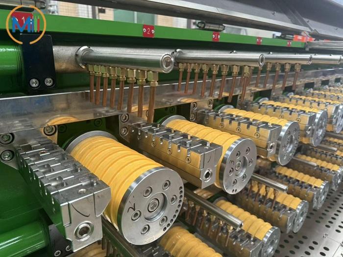
2.1.1 A Multi Wire Drawing Machine is designed to draw several wires simultaneously through a series of drawing dies.
2.1.2 Instead of processing only one wire at a time, the machine uses a shared drawing system to produce multiple wires in a single production cycle.
2.1.3 Depending on the machine configuration, one unit can process up to 40 wires simultaneously. This makes Multi Wire Drawing Machine particularly suitable for manufacturers producing large quantities of fine copper wires for automotive wiring harnesses, electronic equipment, instrumentation cables, and other applications requiring multiple conductors.
2.2 Key Advantages of Multi Wire Drawing Machine
2.2.1 Compact structure and efficient use of floor space
(1) Multi Wire Drawing Machine typically feature a compact horizontal tandem arrangement. Multiple wires are processed within the same machine, reducing the need for separate single-wire drawing units.
(2) This layout helps manufacturers save factory space and simplifies equipment arrangement, especially when several downstream processes need to be connected into a continuous production line.
2.2.2 Multi-motor drive and automated control
(1) Many modern Multi Wire Drawing Machines use multiple motors together with a PLC-based control system. The coordinated drive system helps maintain stable drawing conditions across the production line.
(2) When changing the target wire diameter, operators can replace the corresponding drawing dies and adjust the machine settings according to the production requirements. This can reduce changeover time and lower the amount of manual intervention required.
(3) The resulting improvements in automation can increase production efficiency and reduce operator workload.
2.2.3 Separate lubrication systems for the drawing section and gearbox
(1) The drawing section and gearbox have different lubrication requirements. A well-designed machine separates these areas and uses appropriate sealing structures to reduce the risk of drawing lubricant mixing with gear oil.
(2) This arrangement makes it easier to identify potential leakage, reduces lubricant contamination and waste, and simplifies routine maintenance.
2.2.4 Effective die lubrication and cooling
(1) Drawing dies generate heat and friction during wire reduction. Multi-wire drawing machines commonly use spray lubrication systems to deliver lubricant to the drawing dies and wire surfaces.
(2) Effective lubrication and cooling help reduce friction, limit die wear, and maintain a good wire surface finish. Proper temperature control is also important for stable production and consistent product quality.
2.2.5 Consistent wire diameter and electrical performance
(1) Multiple wires processed through a coordinated drawing system can benefit from consistent production conditions. When the dies, raw materials, drawing parameters, and lubrication system are properly controlled, the machine can produce wires with consistent diameters and surface quality.
(2) For electrical conductors, stable wire dimensions also help maintain predictable electrical resistance and support the quality requirements of downstream cable manufacturing.
2.2.6 High output and lower production cost per wire
(1) A multi-wire drawing machine can produce up to 40 wires simultaneously, depending on the model and configuration. Compared with using multiple single-wire machines to achieve a similar output, this arrangement may reduce equipment investment, floor space, and labor requirements.
(2) In suitable applications, the investment required to achieve the same production capacity can be approximately 40% lower than that of a comparable single-wire machine setup. Actual savings depend on wire specifications, production capacity, equipment configuration, and local operating costs.
(3) Processing multiple wires in one machine can also reduce energy consumption per unit of output under appropriate operating conditions.
2.2.7 Convenient integration with downstream processes
(1) Some multi-wire drawing systems can collect multiple wires on a common take-up spool or use specially designed winding arrangements. This can reduce the number of separate pay-off positions required by subsequent processes.
(2) When integrated with bunching, stranding, or other cable manufacturing equipment, the system can help simplify material handling and improve production-line organization.
2.3 Limitations of Multi Wire Drawing Machines
2.3.1 Despite their advantages, multi-wire drawing machines are not suitable for every application.
2.3.2 If one wire breaks because of inconsistent raw material quality, incorrect operation, or unstable drawing conditions, the machine may need to stop or the production of the other wires may be affected. This can increase downtime and material waste.
2.3.3 The benefits of a multi-wire system are less significant when the production requirement mainly involves single-wire products. In such cases, a single-wire drawing machine may offer greater flexibility.
2.3.4 Multi-wire drawing requires reliable raw materials, suitable drawing dies, and stable lubrication conditions. Frequent wire breaks can reduce overall efficiency and increase maintenance requirements.
2.3.5 For these reasons, manufacturers should evaluate their product range, production volume, wire diameter, raw material quality, and downstream process requirements before selecting a multi-wire drawing machine.
2.4 Typical Applications
2.4.1 Multi Wire Drawing Machines are commonly considered for the production of: Automotive wiring harness conductors, Fine copper wires for electronic equipment,
Instrumentation and control cable conductors, Multiple fine wire conductors for electrical applications, Other high-volume wire products requiring consistent diameter and quality.
2.4.2 Depending on the machine design and wire specifications, the number of drawing passes can typically be selected from approximately 21 to 35 stages.
3.Structure and Working Principles of Single Wire Drawing Machine
3.1 Drawing Section
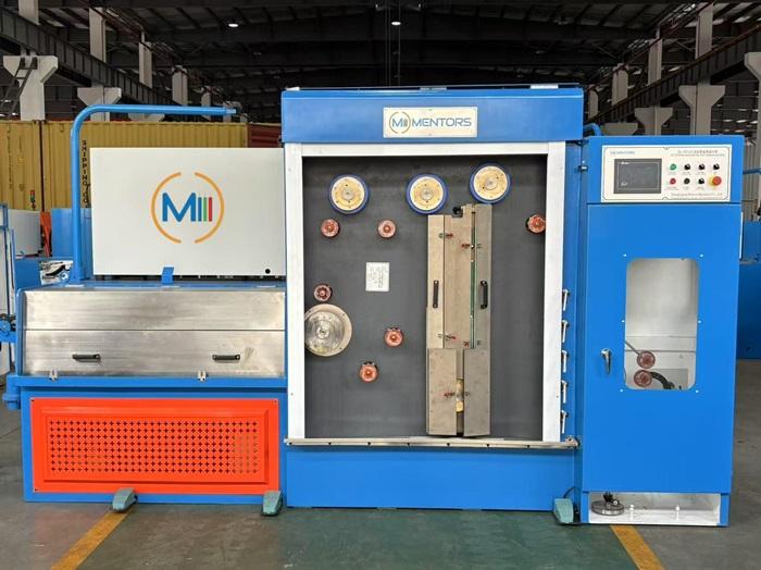
3.1.1 The drawing section is usually divided into front and rear chambers.
3.1.2 The front chamber contains the drawing capstans and die holders, while the rear chamber accommodates the belt transmission components. The machine is generally equipped with protective doors to reduce the risk of drawing lubricant splashing outside the working area.
3.1.3 The capstans are often manufactured from 45# steel with a ceramic coating on the working surface. This combination provides a durable contact surface with good wear resistance.
3.1.4 During operation, the wire passes through a sequence of drawing dies, gradually reducing in diameter until it reaches the required specification. Operators can replace the dies when changing products or when die wear affects wire quality.
3.2 Drive System and Speed Control
3.2.1 The drive system commonly uses a three-phase asynchronous motor combined with multi-stage flat-belt transmission.
3.2.2 A variable frequency drive (VFD) allows operators to adjust the motor speed smoothly within the machine’s operating range. This makes it easier to accommodate different wire diameters, material properties, and production requirements.
3.2.3 Bearings and oil seals are important components of the drive system because they influence mechanical stability, lubrication performance, and service life. High-quality components and proper maintenance help improve the reliability of the machine.
3.2.4 The ceramic-coated capstans provide wear resistance during continuous drawing. Their surface condition should be checked regularly to prevent excessive wear from affecting wire quality.
3.3 Tension Control Mechanism
3.3.1 The tension control mechanism helps maintain stable wire tension between the drawing section and the take-up unit.
3.3.2 A common design uses a mechanical tension arm connected to the take-up motor control system. When the tension arm moves downward, the take-up speed increases. When the arm moves upward, the take-up speed decreases.
3.3.3 This adjustment helps compensate for changes in the wire feed and take-up conditions, maintaining more consistent winding tension.
3.3.4 Stable tension is essential for avoiding loose winding, excessive stretching, and wire breakage. The exact control response depends on the machine design and its electrical configuration.
3.4 Traversing Mechanism
3.4.1 The traversing mechanism distributes the wire evenly across the take-up spool.
3.4.2 A typical system uses a ball screw to move the traversing guide back and forth. The guide support can be adjusted to accommodate different spool widths, while travel limit switches control the movement range.
3.4.3 Proper traversing helps prevent wire overlap, uneven winding, and wire accumulation at the spool edges. These factors are particularly important when the finished wire will be used directly in downstream production.
3.5 Take-Up Spool and Unloading System
3.5.1 The take-up system collects the drawn wire onto a spool. Many small wire drawing machines use a movable unloading trolley and a three-jaw screw clamping mechanism to secure the spool.
3.5.2 This design allows operators to install and remove spools more conveniently. Some configurations also include a full-spool detection system that automatically stops the machine when the spool reaches its preset winding limit.
3.5.3 Automatic stopping helps prevent wire overflow and reduces the risk of damage to the finished product.
3.6 Cooling and Lubrication System
3.6.1 Cooling and lubrication are essential for stable wire drawing. The system typically sprays drawing lubricant onto the wire and dies, while a collection tank gathers the used lubricant for circulation or further treatment.
3.6.2 Adequate lubrication reduces friction, helps control temperature, and extends drawing die service life. Regular inspection of the lubricant condition, filtration system, and circulation equipment is necessary to maintain consistent production performance.
4.Developments in High Speed Wire Drawing Technology
4.1 Increasing production speed is an important development direction in wire drawing equipment. Advances in drive control, die technology, lubrication, cooling, and automatic monitoring have made higher-speed processing possible.
4.2 Actual achievable speed depends on the incoming wire diameter, final wire diameter, number of drawing passes, material properties, die condition, cooling capacity, take-up stability, and required product quality.
4.3 Higher speed alone does not guarantee higher overall productivity. Frequent wire breaks, unstable winding, excessive die wear, or poor surface quality can offset the benefits of faster operation.
4.4 When evaluating a high-speed drawing machine, manufacturers should consider both its maximum rated speed and its ability to maintain stable, continuous production under normal operating conditions.
5.How to Select Suitable Wire Drawing Machine
5.1 Selecting the right wire drawing machine requires more than comparing maximum line speeds or initial purchase prices.The following factors should be considered.
5.2 Wire material: Copper, aluminum, and other materials have different drawing characteristics.
5.3 Incoming and finished wire diameters: These determine the required reduction ratio and number of drawing passes.
5.4 Production capacity: High-volume production may benefit from multi-wire drawing, while smaller or more varied orders may favor single-wire equipment.
5.5 Automation requirements: Automatic tension control, spool changing, and full-spool detection can reduce manual intervention.
5.6 Surface quality requirements: Drawing dies, capstan surfaces, lubrication, and cooling all influence the finished wire.
5.7 Downstream compatibility: The take-up arrangement and production speed should match the requirements of bunching, stranding, annealing, or extrusion equipment.
5.8 Maintenance and operating costs: Spare parts, lubricant consumption, energy use, die replacement, and downtime should all be considered.
5.9 A machine that offers the highest rated speed may not be the most economical choice for every factory. Stable operation, product consistency, and compatibility with the complete production process are equally important.
6. Conclusion
Wire drawing technology continues to develop toward higher production efficiency, improved automation, and better integration with downstream manufacturing processes.
Multi wire Drawing Machines offer advantages in compact layout, high output, and efficient production of multiple wires. Single Wire Drawing Machines provide a practical solution for manufacturers that require flexible operation and straightforward equipment structures. Meanwhile, developments in high-speed drawing technology are expanding production possibilities for copper wires, although actual performance depends on the specific application and operating conditions.
For wire and cable manufacturers, the best equipment choice is the one that matches their product specifications, production volume, quality requirements, and factory layout. By evaluating the entire production process rather than a single machine parameter, manufacturers can build more efficient, reliable, and cost-effective wire drawing operations.
Click here to see the running video of the Multi wire Drawing Machine
NOTE:All rights reserved, Reprinting is prohibited without permission.