
1.Adjustment of Wire Drawing Machines
1.1 Initial Adjustment Before Starting a New Machine
Before putting a newly installed Wire Drawing Machine into production, the following preparations and adjustments should be completed.
1.1.1 Pneumatic and Lubrication Systems
Connect the compressed air supply and ensure that lubricating oil is delivered to all designated lubrication points. Fill the gearbox with the specified lubricating oil according to the oil level markings.
1.1.2 Cooling and Circulation System
Connect the cooling water supply and return pipes. Prime the lubrication system with the required drawing lubricant and check that all circulation pipelines are properly connected and free from blockages. Refer to the supplied machine drawings to verify that the pipeline connections are correct.
1.1.3 No-Load Test Run
After installation, each individual component should be operated separately for an initial test. Once all components have been checked, perform a complete machine no-load test.
Run the machine at a medium speed for 6 consecutive hours. During this period: (1)Stop the machine every hour to check whether any fasteners have become loose. (2)Check the temperature rise of the bearings, which should not exceed 40℃.
(3)Inspect the braking mechanism and make necessary adjustments.
(4)Check all lubrication and cooling connections for oil or water leakage.
Only after the no-load test has been completed successfully should the machine proceed to production testing.
1.1.4 Production Parameter Adjustment
After starting the machine, adjust the drawing main motor, capstan motor, and take-up system to ensure synchronized operation and constant take-up tension.
Select suitable drawing dies according to the required wire specifications and drawing process. Determine the appropriate production speed based on the selected die configuration and drawing reduction ratio.
During production, operators should continuously monitor the synchronization between the main motor, capstan motor, and take-up system. If speed differences or unstable take-up tension occur, make timely adjustments until the machine operates smoothly and consistently.
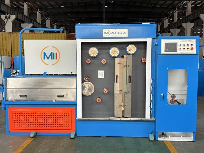
1.2 Adjustments During Machine Operation
Different machine components require appropriate adjustments according to the wire specifications and production conditions.
| Adjustment Item | Requirements | Possible Problems if Improperly Adjusted |
| Guide Wheels and Traverse System | Adjust the traverse pitch according to the wire diameter. Match the main machine speed with the take-up and pay-off speeds. Adjust the tension control system as required. | Irregular wire winding, overlapping wires, and disordered spooling. |
| Drawing Capstans and Rims | For large drawing machines, worn capstans or rims may be reversed for continued use when their structure permits. Replace them when wear becomes excessive. | Surface scratches, dimensional deviations, and unstable wire drawing quality. |
| Die Holder Center Position | Correct the center position of the die holder to ensure proper alignment and a straight wire drawing path. | Uneven die wear, wire breakage, and excessive wire ovality. |
2.Maintenance of Wire Drawing Machines
2.1 Pre-Operation Inspection
Before each production shift, operators should carry out the following checks.
2.1.1 Mechanical Components
Check the transmission components and safety guards to ensure they are properly installed and in good condition. Check that the gearbox oil level is within the specified range.
2.1.2 Pneumatic and Lubrication Pipelines
Inspect the compressed air pipes, drawing lubricant pipelines, and lubrication lines for leakage or blockage.
Check whether the air supply is sufficient and whether the air pressure meets the required operating conditions. Drain accumulated water from the air-water separator when necessary.
The air-water separator removes condensed moisture from the compressed air. If accumulated water is not drained regularly, it may enter the pneumatic control system and damage components such as tension control cylinders and solenoid valves. This can result in unstable drawing tension and frequent wire breakage.
2.1.3 Air Filter and Lubricator
Inspect the pneumatic system’s air filter and ensure that the lubricator contains sufficient oil to provide proper lubrication to pneumatic components.
2.1.4 Drawing Lubricant and Heat Exchanger
Regularly check and replenish the special drawing lubricant used for copper and aluminum wire drawing.
Clean the metal dust accumulated inside the machine guards every two months. Clean the heat exchanger regularly to maintain effective heat dissipation.
When the machine is not in production for an extended period, drain the drawing lubricant from the relevant system when required by the machine design and maintenance instructions to prevent lubricant deterioration or blockages.
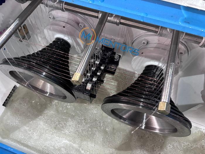
2.1.5 Gears and Gear Pumps
Regularly inspect the gears and gear pumps, particularly on large and intermediate Wire Drawing Machines equipped with gear-driven transmission systems. Check the lubrication condition and replace the lubricating oil according to the recommended maintenance schedule.
2.2 Scheduled Maintenance
2.2.1 Machine Maintenance Form
| Maintenance Level | Maintenance Items | Frequency |
| Daily Maintenance | Clean the machine; check the fastening condition of rotating components before starting; remove copper scraps, aluminum scraps, and wire ends from the take-up area; lubricate cylinders, lead screws, and guide rails; check for loose fasteners. | Every shift |
| Periodic Maintenance | Clean the three-stage filter screens in the drawing lubricant circuit and the mesh filter; replenish mechanical oil for the lifting guide rods; inspect cylinders and piston rods. | Every 15 days |
| Annual Overhaul | Carry out a comprehensive inspection and maintenance; replace gearbox lubricating oil; inspect and replace worn mechanical components as necessary. | According to operating hours and machine condition |
2.2.2 In addition, the filter elements in the gear lubrication oil tanks should be inspected and cleaned or replaced when necessary. These filter elements are used in the lubrication systems of intermediate and large wire drawing machines, including 8-head and 16-head machines.
2.2.3 For intermediate drawing machines equipped with externally mounted gear oil pumps, special attention should also be paid to the condition of the oil pump and its filtration system.
3.Common Problems and Troubleshooting
| Fault Description | Possible Causes | Recommended Solutions |
| Finished wire does not meet the required specifications. | Incorrect drawing die configuration; mismatched machine speeds. | Replace the dies with suitable specifications and recalibrate the machine speeds. |
| Wire breakage during production. | Incorrect brake clearance; worn brake wheel; insufficient bearing lubrication or damaged bearings. | Adjust the brake clearance, replace the worn brake wheel, replenish lubricating oil, or replace damaged bearings. |
| Guide wheels do not rotate smoothly. | Insufficient bearing lubrication or bearing wear. | Lubricate the bearings or replace them if necessary. |
| The entire machine cannot start. | Emergency stop button not reset; faulty door limit switch; abnormal lubrication supply. | Reset the emergency stop button, inspect the door limit switch, and check the lubrication supply system. |
| Jog operation is unavailable during wire threading. | Limit switch displacement or travel limit exceeded. | Readjust the limit switch position and check its operating range. |
| Excessive oil leakage at the input or output end of the haul-off unit. | Lubrication pipeline malfunction. This issue mainly occurs on gear-driven intermediate and large wire drawing machines. | Open the inspection window on the upper part of the gearbox and check and adjust the lubrication circuit to reduce excessive oil leakage. |
| Wire oxidation between annealing wheels. | Incorrect annealing unit dimensions; abnormal water levels in the water seal tank or steam protection tank; air entering the annealing zone. | Check the machining dimensions of the annealing wheels, adjust the water levels in the sealing and steam protection tanks, and check the protective gas supply to minimize air entry into the annealing tube. |
4.Key Points for Proper Machine Maintenance
4.1 Complete No-Load Testing Before Production
A newly installed machine must undergo a 6-hour continuous no-load test. Stop the machine at regular intervals to inspect fasteners, bearing temperatures, and possible leakage. Production testing should only begin after the no-load test is satisfactory.
4.2 Maintain Proper Speed Synchronization and Drawing Tension
The drawing main motor, capstan motor, and take-up system must operate in coordination. Incorrect speed matching or unstable tension can lead to wire breakage, dimensional variations, and poor winding quality.
4.3 Keep the Filtration System Clean
The filtration system plays an important role in protecting drawing dies and reducing wire surface scratches. Clean the three-stage filter screens in the drawing lubricant circuit and the mesh filters every 15 days. Regularly inspect the filter elements in the gear lubrication oil tanks, especially on intermediate and large Wire Drawing Machines, including 8-head and 16-head models.
4.4 Follow a Regular Maintenance Schedule
Daily inspections should focus on oil levels, air pressure, filters, lubrication conditions, and accumulated metal dust. Clean the machine and check critical components every shift. Periodic maintenance and annual overhauls should be carried out according to the machine’s operating conditions.
4.5 Identify Faults and Take Corrective Action Promptly
When wire breakage or poor wire quality occurs, first check the drawing die configuration, braking mechanism, guide wheel bearings, travel limit switches, and lubrication system. Early identification and proper maintenance can help minimize downtime and maintain consistent production quality.
5. Conclusion
Proper adjustment and regular maintenance are essential for the reliable operation of Wire Drawing Machines. By following the recommended inspection procedures, maintenance schedules, and troubleshooting methods, operators can reduce unexpected equipment failures, improve wire drawing quality, and extend machine service life.
We Mentors believe that proper equipment maintenance is an important part of achieving efficient and stable wire production.
Click here to see the details of the Wire Drawing Machine
Click here to see the running video of the Wire Drawing Machine
NOTE:All rights reserved, Reprinting is prohibited without permission.